Pete's Log: What's wrong with this circuit?
Entry #1968, (Smokepacking)(posted when I was 42 years old.)
JB has returned to daycare and I have returned to staying up too late playing with electronics.
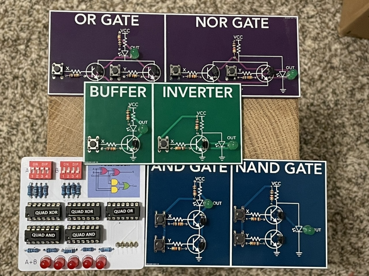
I want to make some PCBs. I have a couple projects in mind. But I want to start small to figure out what I'm doing. My mid-month HackerBox came with some fun simple logic gate PCBs that I soldered together today. They can be seen below along with the full adder I previously mentioned.
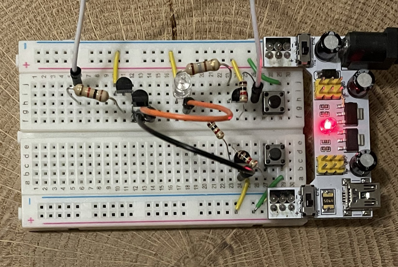
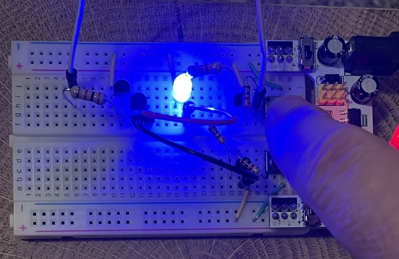
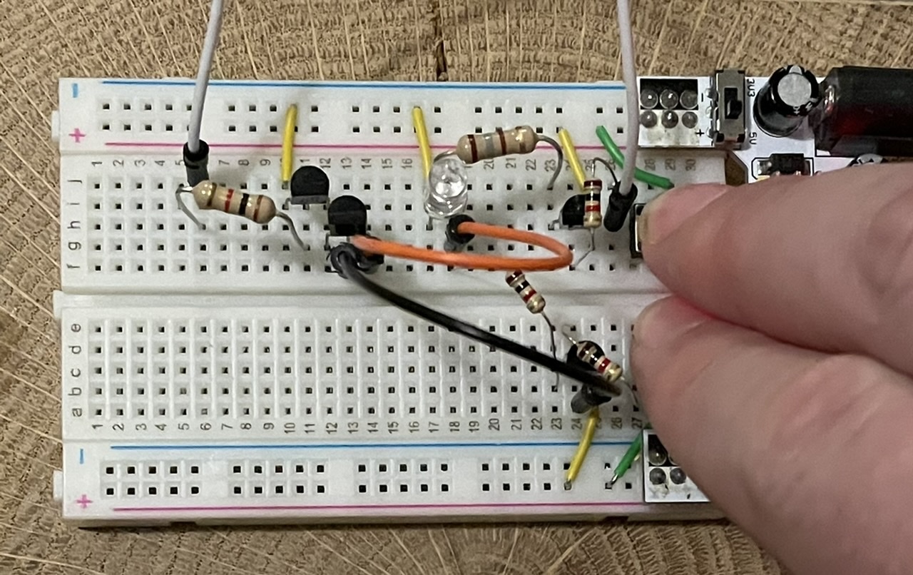
Since the full adder uses XOR gates and this PCB set didn't include XOR, I thought a similar XOR PCB would be a fun first PCB project. So step one, prototype it on a breadboard. (As an aside, I am quite pleased to have enough transistors in my supply to prototype this.) The HackerBoxes PCBs all use 2N2222A NPN transistors to build the logic, so I figured I would do the same. I decided to lay out a circuit myself before duckduckgo-ing the answer. I came up with this:
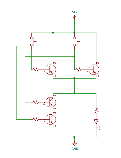
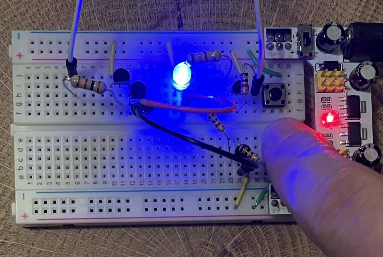
And it seems to work:
But after checking online, I can't seem to find the same approach. Granted, it's late so I'm not terribly motivated to search for a long time. But it makes me feel like I need to spend some more time on fundamentals. But I don't have time for that. :D
Anyway, this might work just fine for what's really just intended as a "hello world" PCB. On another note, KiCAD is fun. It reminds me of my VLSI days.