Pete's Log: Practicing Soldering
Entry #1912, (Smokepacking)(posted when I was 42 years old.)
Recently I described my HackerBoxes subscription as "mostly aspirational" and added that I "hope in a couple years JB will want to learn soldering."
While time remains the main limiting factor, feeling slightly anxious about soldering is another. So far most kits haven't asked for much more than soldering headers onto boards, which isn't usually a problem. But just the idea that soldering is involved seems to greatly increase how much time I think I'll need to do something.
In any event, the latest HackerBox, #64 has significantly upped the soldering ante. And since it looks real neat and since I can't teach JB soldering if I'm not comfortable with it, I decided now was the time to start practicing.
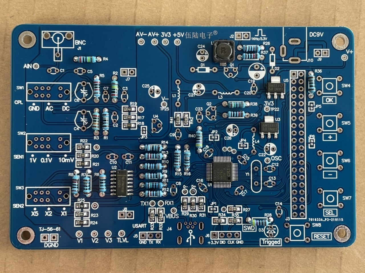
HackerBox 64 includes a JYE Tech DSO 138 Oscilloscope DIY Kit. The surface-mount components were already in place, but all the through-hole components were SIY (solder-it-yourself). The kit includes roughly 80 through-hole components, with anywhere between two and twenty leads each. So plenty opportunity to practice. And JB was at Jamie's parents on Saturday, so the time seemed right. The idea of doing this much soldering without being able to test my work until the end was daunting, but in I jumped.
Below is the circuit board after adding all the resistors. It took me about two hours to get to this point. I wasn't rushing and probably had a couple breaks, but that's roughly five minutes per resistor. Not exactly high speed.
Another two hours later (which included breaking for dinner), I had the inductors, capacitors and diodes added as well:
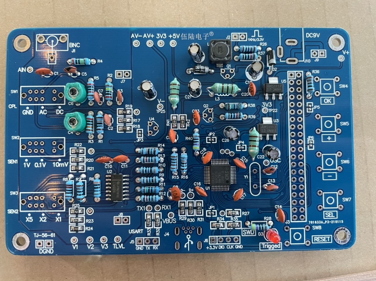
Another hour and I was just about done soldering:

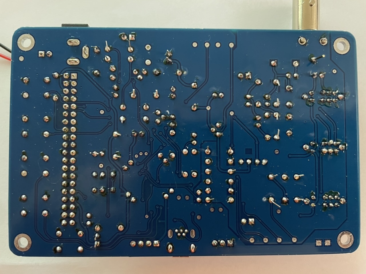
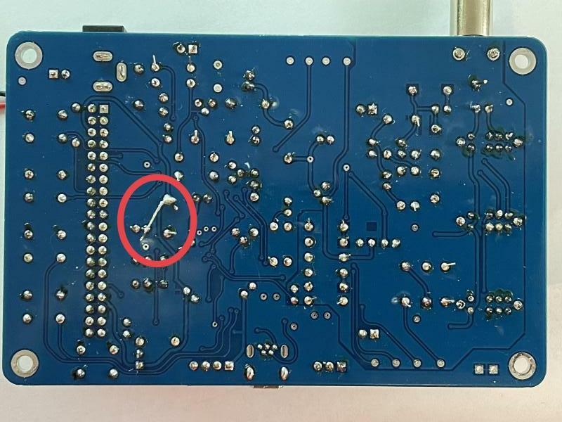
And here's the back, which looks nowhere near as neat as I wish it did.
One nice feature of this board is they include a few jumpers to isolate various bits of the circuit from each other. So you can test that the power supply components are working before you let more sensitive parts of the board get powered.
The HackerBox came with a 9V battery adapter cable, so that was the quickest thing to grab for a power up test. And nothing happened. I got a couple small voltage readings on the board, but nothing near what I should have been seeing. After longer than I care to admit, I finally decided to test the battery and the cable from the battery to the board. The battery was fine, but the cable connecting the battery to the board was not. Since this was a new adapter that came with the HackerBox, that was a bit of a bummer.
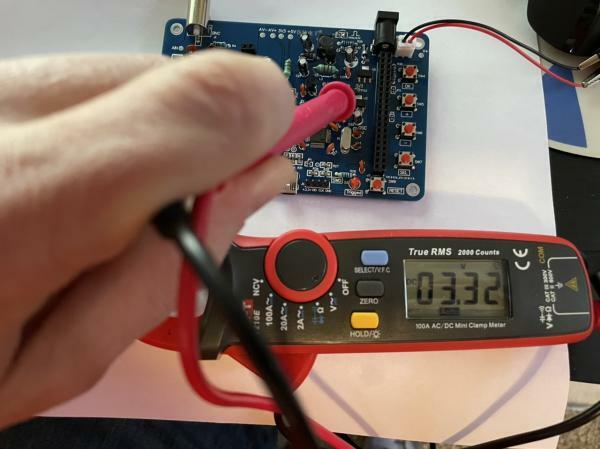
Anyway, I next did what I should have done in the first place and hooked the board up to my lab power supply on my desk. And hooray, the test point that was supposed to measure 3.3V did!
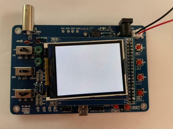
The next step was to solder a jumper to connect the rest of the board to power. So I did that. And then attached the screen and powered it up again. And just got a blank white screen.
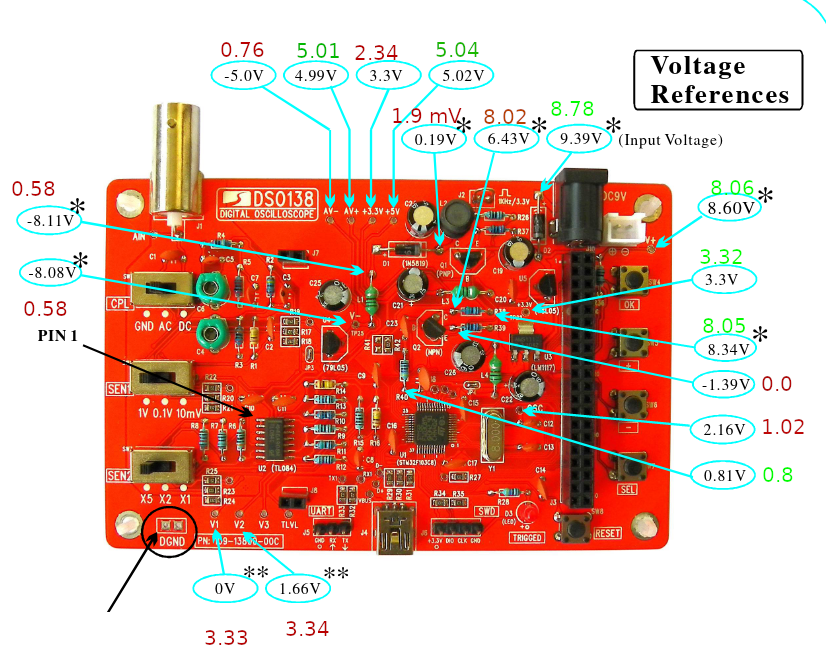
I followed some of the suggested debugging steps but none of them seemed to apply to me. Also, the JYE Tech forums were down due to a MySQL connection error, so that ruled out a bunch of search results. But the manual included a nice voltage reference chart, so I followed along and noted what I was seeing and where I was off.
This exercise led me to realizing that the jumper I had soldered was actually still open. My one complaint about this board is that the jumper is surrounded by several components, making it tricky to get to with my skill level. After several attempts I finally gave up and utilized an unprofessional workaround. I traced which components were connected to either side of the jumper and then soldered a lead between them:
That did the trick!
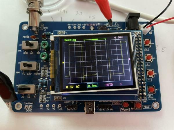
The board comes with a test 1kHz square wave test signal for calibration, which is another nice feature. I do have a bit of overshoot on the leading edge of the signal. There is a trimming capacitor on the board that is supposed to allow me to adjust that, but it doesn't seem to do anything, so that is something to look into. But as a soldering exercise, I feel satisfied with the result. It's not pretty and I have more practicing to do, but it's mostly working! Although I have decided I want some better soldering gear. :D
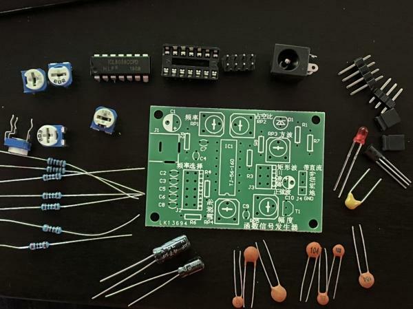
This HackerBox also came with a signal generator kit, so I have more soldering practice ahead of me:
Epilogue
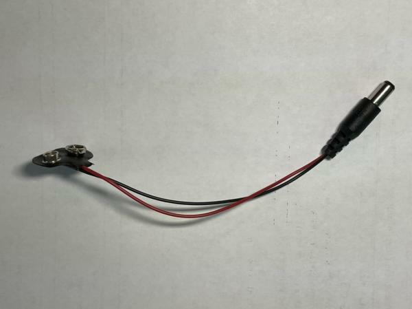
This is the 9V battery adapter that gave me trouble:
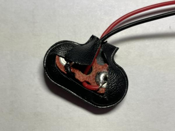
A quick continuity test showed me the positive connection isn't working. I opened up the battery end, since that was easy to get open and I hoped maybe there'd be an easy fix there. Alas, the connections on that end looked fine.
I peeled off some of the insulation on the positive wire and verified that a continuity test to the battery end was fine, but to the jack end was not. So maybe a future project will be to see if I can get the jack open somehow to fix the connection. Or maybe I'll just cut the jack off and use this as sort of a loose 9V battery connector. In my supply bins I do have several more of these that do work (had to test them after this issue) so there's no real sense in fixing this one other than for practice.
Anyway, I give the DSO138 a thumbs up. It's a neat little board and it's portable. Now I have three oscilloscopes (of which two even work!)